
If your factory handles heavy, awkward, or fragile parts daily, a zero gravity pneumatic manipulator can turn precise placement into a smooth, human‑guided motion—without the sway and lag of ropes or chains. This guide explains how a zero gravity pneumatic manipulator works, why pneumatic reliability matters in dusty/oily/high‑frequency environments, and how to apply it in sheet metal, glass/photovoltaic, and drums/chemicals workflows. It’s written for industrial engineers, EHS specialists, and production leaders who need practical, application‑level detail—selection criteria, EOAT choices, commissioning, maintenance, and when to choose alternatives such as hoists or cobots.
1) How a zero gravity pneumatic manipulator works
At its core, a zero gravity pneumatic manipulator balances the weight of the tool and payload using compressed air so the operator feels near‑neutral force in “float” mode. The arm’s cylinders and load‑sensing valves counteract gravity in real time. With balance tuned correctly, you nudge the handle, the part follows with millimetric finesse, and when you stop, it holds steady without drift.
Most systems separate two balancing circuits: one for the arm and EOAT (no‑load), another for the payload (load). This split keeps motion predictable whether you’re grasping a part or traveling empty. Articulated arms provide horizontal reach and guided vertical lift, with optional tilt/rotation axes at the end effector. If you need a concise primer on fundamentals, see this overview of the principles behind a pneumatic manipulator.
In practice, operators switch between lift/float/park states using an ergonomic handle with enable logic. Good designs also incorporate grip‑before‑lift interlocks (e.g., vacuum OK or clamp confirmed) and spring‑applied, air‑released brakes that “park” safely when the device is idle or the line E‑stops. Think of it this way: you’re adding an intuitive, gravity‑cancelling “power steering” layer to manual handling—fine control stays in human hands, but the heavy lifting is offloaded to pneumatics.
2) Reliability in dusty, oily, high‑frequency use
Harsh environments are where a zero gravity pneumatic manipulator earns its keep. Dust can score seals and clog valves; oil mist can foul pads and reduce vacuum friction; high‑frequency cycling can expose weak points in air quality and lubrication. Reliability starts at the air source and propagates to every valve and actuator downstream.
Air quality and preparation
- Specify filtration and dryness consistent with your components and duty cycle. As a rule of thumb, target coalescing filtration and a pressure dew point that avoids condensate in your ambient temperature.
- Keep regulator settings consistent and add a bit of margin above the maximum working requirement so brief demand spikes don’t starve the circuit.
- Drain bowls and condensate routinely; water in lines is the fastest route to sticky spools and sluggish response.
Seal materials and valves
Use component seals and valve families proven for your contaminants and temperature range. In oily atmospheres, clean EOAT pads and magnet faces more frequently to maintain grip coefficients. Where cycle counts are high, standardize spare kits and quick‑change EOAT liners so consumables don’t become downtime drivers.
Fail‑safe behavior
Loss‑of‑air events should result in a controlled hold, not a drop. That’s handled by check/lock valves in lift circuits, spring‑applied brakes, and low‑pressure inhibits that block risky motions. During commissioning, simulate pressure loss with a rated test load and document results as part of the handover pack.
3) EOAT by application: sheet metal, glass/solar, drums/chemicals
End‑of‑arm tooling (EOAT) makes or breaks your outcome. Below are proven patterns by application, keeping the zero gravity pneumatic manipulator’s float behavior intact while adding the contact mechanics you need for quality and safety.
Sheet metal loading — laser, press brake, deburr
For smooth, non‑perforated sheets, use vacuum cups sized to distribute load with room to avoid holes or edge scallops. On oily or perforated steel, magnetic grippers can stabilize pickup where vacuum would leak; many teams adopt hybrid arrays—magnets for pickup stability plus cups for placement damping and anti‑marking. Include edge guards or soft spacers where the part rides near finished surfaces. Plan for 90° tilt or 180° rotation if orientation changes are frequent, and model center‑of‑gravity offset for long plates so lift doesn’t induce nose‑down moments.
Glass and photovoltaic panels
Use high‑flow vacuum pads with soft, mark‑free materials and, where appropriate, floating or low‑vacuum designs that reduce surface stress. Spread pads to avoid bending moments on thin panels and incorporate redundant circuits with check valves so one leak doesn’t trigger a release. For vertical moves or long carries, add mechanical guides or bumpers that keep corners protected without rubbing the face.
Drums, pails, and bags in chemicals
For rigid containers, expanding‑core mandrels (capturing the inner lip) or band clamps with lined jaws provide secure grip. Where tilt/pour is needed, integrate 0–180° or continuous rotation with a positive lock at common angles. In corrosive areas, specify stainless or coated components and maintain interlocks that verify a locked grip before lift. For flexible bags, control expectations: use hooks or cradles and keep lift paths short to avoid pendulum effects; zero‑gravity float helps you land gently on pallets without burst risk.
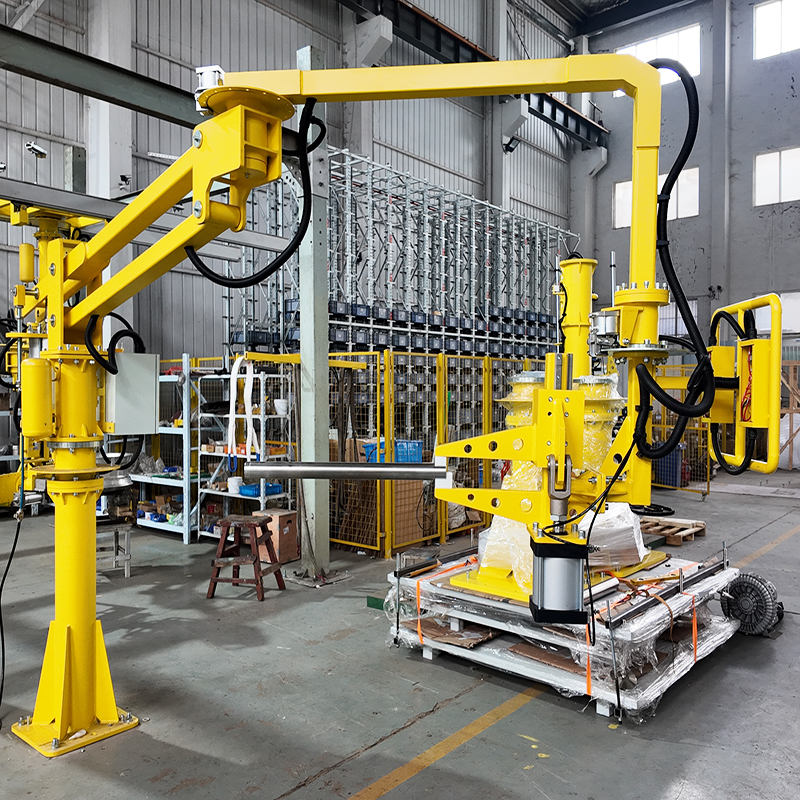
For a visual summary of product‑level options and typical working envelopes, review this neutral overview of a zero gravity pneumatic manipulator configuration. It shows how custom EOAT and stroke choices adapt to different parts while keeping float control consistent.
4) Selection and sizing checklist
Getting the specification right ensures your zero gravity pneumatic manipulator behaves the way operators expect on Day 1—and Day 1,000. Use the checklist below to capture the variables that control balance, stability, speed, and reach.
- Payload window and inertia: Specify min/typical/max payload, EOAT mass, and any moments created during tilt/rotation. If your mix varies widely, confirm that balance valves and springs support both ends of the range.
- Geometry: Define horizontal reach (min/nominal/max) and required vertical stroke, including clearance for fixtures and carts. Note aisle widths and interference risks.
- Duty cycle and takt: Peak and average cycles per hour shape valve sizing, cooling, and air consumption assumptions. Align to station takt with a margin for rework.
- Air supply and prep: Pressure range, dryer type, filtration grade, and hose/cable management. Record drop across the run at peak flow.
- Mounting and travel: Column‑mounted for single stations; overhead rail or gantry when you must span multiple cells or large work envelopes.
- Handle and controls: Choose between discrete up/down vs true float/proportional control; define enable/confirm logic, speed limits, and park behaviors.
- Safety interlocks: Grip‑before‑lift, low‑pressure inhibit, emergency stops, and brake strategy. Document the test plan you’ll execute at commissioning.
| Parameter | Typical choice | Notes |
|---|---|---|
| Payload range | 40–120 kg | Include EOAT mass and max CG offset |
| Vertical stroke | 1.5–2.0 m | Add clearance for fixtures and carts |
| Control style | Proportional float | Best for fine alignment by hand |
| Mounting | Column + overhead rail | Covers multiple adjacent stations |
| Safety | Grip interlock + spring brake | Validated during air‑loss test |
5) Installation, commissioning, and operator training
A well‑planned handover is the difference between “it moves” and “it works the way we hoped.” Treat commissioning as a structured validation of the zero gravity pneumatic manipulator’s behavior across your full load range.
Air validation and FLR setup
Verify inlet pressure under load, dew point suitable for ambient, and flow capacity at peak demand. Install non‑return valves where needed to hold state during transient drops. Set regulators with a small positive margin above worst‑case demand and confirm filtration elements are new and labeled with the replacement interval.
Functional and safety tests
With a rated test load, run step‑response checks on lift/lower to validate valve health and speed limits. Confirm grip‑before‑lift logic by simulating a failed grip signal; the device should refuse to lift. Cut air to simulate a loss‑of‑air event; the load should remain supported by lock valves and/or spring brakes. Document outcomes with photos and signatures; it’s part of the technical file and operator confidence.
Mechanical checks and ergonomics
Inspect column/rail fixings to drawings, check end‑stop clearances, and exercise the arm through the entire envelope to spot hose snags or pinch points. Tweak handle height, resistance, and control ergonomics so operators don’t overreach. A crisp interface and consistent “feel” reduce training time and error rates.
Operator training and handover
- Walk through balance/float tuning for both empty and loaded states.
- Review daily pre‑use checks (pressure, drain, visible leaks, pad/magnet cleanliness) and safe parking positions.
- Establish a simple fault‑reporting routine and define who owns pad/liner replacement.
6) Safety, maintenance, and lifecycle practices
Safety engineering is built into the device, but it’s verified—and kept healthy—by routine checks. Adopt a preventive rhythm that matches your environment’s severity and duty cycle.
Maintenance rhythm
Daily/shift: Drain water, verify pressure and grip/brake function, wipe pads/magnets, and inspect hoses/fittings.
Monthly/quarterly: Replace clogged filters, calibrate regulators, and test emergency stops and air‑loss lock.
Annually/major: Inspect cylinder seals and replace as per the component schedule; replace hoses proactively in oily or UV‑exposed areas. Keep a simple log at the cell; trends reveal issues before they bite.
Troubleshooting cues
Sluggish lift/lower suggests contamination or regulator creep; drift at hold points to a balance mis‑tune or internal leakage; recurring vacuum alarms to pad wear or seal damage. Address root causes, not just symptoms, and close out with a functional test so operators trust the fix.
7) Practical workflows and mini case studies
Automotive final assembly with human‑in‑the‑loop control
A door‑installation station needed millimetric alignment to mating hinges with a 60–90 kg door module. A zero gravity pneumatic manipulator with proportional float and a hinge‑datum EOAT allowed the operator to “float” into the pins without fighting gravity. Grip‑before‑lift interlocks prevented pick unless clamps were fully locked, and a spring‑applied brake parked the tool between vehicles. For reference on typical fixtures and ranges, see an automotive door assembly manipulator configuration. In a similar program, TIANSHILI supported a mixed‑model line by pairing a balanced folding arm with fixed hard‑stops on the EOAT, letting one operator meet takt across two adjacent variants with consistent ergonomics.
Glass and photovoltaic handling
Large panels were marking under suction at tight vacuum levels. Swapping to soft, mark‑free pads and distributing them on a light frame reduced local stress. Redundant vacuum channels with check valves maintained hold during brief leaks while the float mode helped the operator “feather” contact onto locating pins.
Drums and chemicals with tilting
An indoor transfer cell needed 180° tilt to decant viscous material into a mixer. An expanding‑core mandrel secured the rim, with an interlocked tilt axis that refused motion unless the grip sensor was true. Zero‑gravity float made it easy to stop at intermediate angles and settle gently at setpoints.
Integration across larger envelopes
When the work envelope spans multiple cells or you need long travel with consistent handling, pair the manipulator with overhead motion. For context on spanning multi‑station layouts, here’s an overview of gantry robot integration for large work areas. While gantries are fully automated in many applications, the same rail concepts can carry a human‑guided manipulator to extend coverage without sacrificing float control.
Post time: Mar-23-2026