
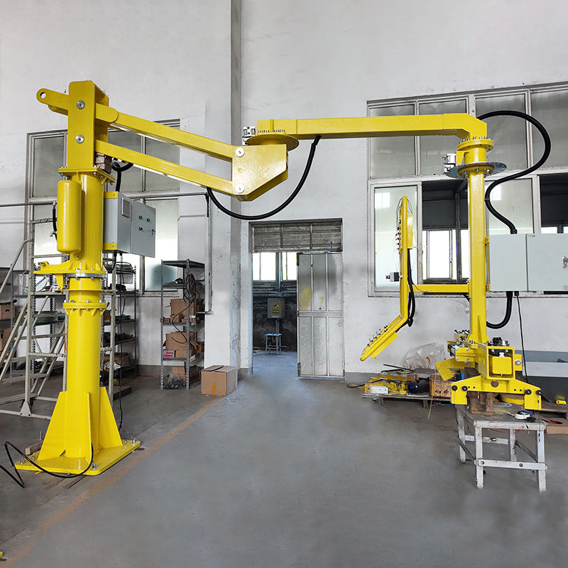
The working principle of a Pneumatic Manipulator Lifting System revolves around a simple yet highly effective goal: tricking physics to create a “zero-gravity” (weightless) state.
By utilizing a continuous, finely regulated supply of compressed air, the system matches the gravitational pull of a heavy load with equal and opposite pneumatic force. This allows a human operator to lift, lower, and manipulate objects weighing hundreds of kilograms with the effortless push of a finger.
1. The Fundamental Physics: Force Balancing
At the heart of the system is a precision pneumatic cylinder integrated into a rigid mechanical arm. According to fluid mechanics, the lifting force generated by the cylinder is a function of air pressure and piston geometry.
2. The Dual-Circuit Logic: How It Thinks
A pneumatic manipulator doesn’t just use a single static air pressure; it relies on a dual-circuit balancing system managed by pilot-operated regulators.
A. No-Load (Tare) Balance Circuit
When the manipulator is moving empty (without a workpiece), the pneumatic circuit switches to a low-pressure setting. This pressure generates just enough force to counteract the dead weight of the articulated arm and the end-effector (gripper). The arm floats weightlessly in mid-air; if the operator lets go, it remains perfectly stationary.
B. Loaded Balance Circuit
The moment the gripper clamps onto a payload (e.g., a car door, a sheet of metal, or a chemical drum), a sensor triggers a switch to the high-pressure circuit. This injects a precisely calibrated volume of air into the cylinder to account for the new mass. The combined weight is instantly neutralized, returning the system to an equilibrium state.
3. Operator Interaction: Moving the Load
Once the load is perfectly counterbalanced, the operator can maneuver it using one of two methods:
-
Intuitive Handle Control (True Float Mode): The operator pushes or pulls directly on the workpiece or the control handle. A highly sensitive proportional valve detects this manual input. If the operator pushes down, the valve vents a minute amount of air, causing the arm to sink smoothly. If they pull up, it adds air. The operator feels less than 2 kg of structural resistance.
-
Pneumatic Lever/Toggle Command: For simpler setups, the handle features a traditional up/down proportional lever. Pressing the lever alters the pilot pressure, forcing the main cylinder to actuate at a controlled velocity.
4. Built-In Safety Fail-Safes
Because compressed air is naturally elastic, specialized safety valves are mandatory to prevent catastrophic failures:
-
Air-Loss Safeguard: If a factory main air line ruptures, specialized one-way check valves trap the air inside the manipulator’s lifting cylinder. Instead of crashing down, the arm is locked in place or undergoes a slow, controlled descent to the floor.
-
Anti-Rebound / Load-Loss Protection: If a heavy component slips out of a clamp or a vacuum cup loses its seal in mid-air, a traditional hoist would dangerously rocket upward due to the sudden loss of mass. Pneumatic manipulators utilize instant cutoff valves that lock the vertical axis within 10 ms of detecting an unexpected pressure mismatch, protecting the operator.
Are you looking to design or specify a pneumatic system for a fixed-weight payload (which uses a simpler manual preset regulator), or do you need a dynamic system capable of automatically adapting to variable load weights?
Post time: May-18-2026