
If fixture loading and unloading is throttling your machining or assembly cell—and operator fatigue or strain is creeping up—there’s a practical middle path between a simple hoist and a fully automated robot. A manual gantry type manipulator gives you broad X–Y coverage with a guided Z lift so operators can align awkward or heavy parts into jigs with confidence, consistency, and lower effort. This guide walks you through when to choose one, how to size it, and what to verify for ergonomics and safety.
What is a manual gantry type manipulator?
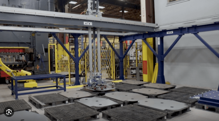
A manual gantry type manipulator is a workstation handling system built on overhead rails (X–Y) with a carriage that supports a lift axis (Z) and an end‑effector. Motion is guided by the operator—sometimes with light power‑assist on lift or traverse—rather than by programmed automation. The goal is precise, low‑effort placement within a large rectangular envelope without the cost and rigidity of a robot cell.
How it differs from a gantry robot: a gantry robot executes programmed paths at higher speeds and repeatability for consistent SKUs and volumes. A manual gantry type manipulator prioritizes human control for variable parts, frequent changeovers, and close‑tolerance insertions into fixtures. If you need a primer on robotic gantries to understand the contrast, see the overview of Cartesian systems in the gantry robot context.
When a manual gantry type manipulator is the right choice
Use the following decision rules to judge fit against common alternatives for fixture loading/unloading in machining and assembly:
- Use a manual gantry when operators must align parts into nests or vises with visual feedback, payloads are light‑to‑medium, and SKUs or fixtures change often.
- Prefer a jib crane where the work envelope is small and mostly vertical, with minimal horizontal travel between pickup and the machine.
- Consider an electric hoist (with trolley) if vertical lifting is the primary need and X–Y travel is short or handled by a simple beam; see this powered‑lift option for context on electric hoist manipulators.
- Choose a pneumatic balancer when “float” feel and fine manual positioning of lighter payloads outweigh the need for long X–Y coverage.
- Step up to a gantry robot if volumes are high, parts are consistent, and unattended cycles justify automation engineering.
Selection criteria for fixture loading/unloading
Getting the specification right up front prevents operator strain and rework later. Work through these factors in order.
- Duty cycle and environment
- Define cycles per hour, shifts per day, and peak periods. Heat, coolant mist, chips, dust, or weld spatter influence rail protection, bearings, and seals. Classify expected service to guide component selection and inspection frequency.
- Payload and center of gravity (COG)
- Capture the heaviest part plus fixture adapters and the end‑effector mass. If the COG is offset from the Z carriage, include the resulting moment in sizing the bridge/rails and end‑effector mount. Account for dynamic factors from starts/stops and any required tilt/rotation.
- Rail span and deflection
- The bridge beam spanning between runways must deflect minimally under load to avoid “sag” that complicates fixture insertion. A practical limit for many workstation bridges is on the order of L/600 (span/600) or tighter. Increasing the section modulus (I), shortening span, or distributing load reduces deflection.
- Stroke and travel
- Vertical Z stroke should clear pickup and machine door heights with safety margin. X–Y travel should cover pickup, staging, and machine infeed with room for operator stance. Plan for future fixtures—an extra 10–20% envelope often prevents costly changes.
- End‑effector and motions
- Match the gripping principle to the part and fixture: mechanical clamps/jaws for irregular shapes or positive retention; vacuum for flat, sealed surfaces; magnets for ferrous plates/blocks. Decide if you need in‑hand rotations or tilts for orientation. Quick‑change adapters help if SKUs vary.
- Ergonomics and safety
- Verify push/pull forces to initiate and sustain motion are within reasonable ergonomic guidelines for your workforce and floor conditions. Provide E‑stops, clear signage, and training. Avoid side pulls and shock loads. Where people and equipment mingle, design for visibility and safe clearances.
For deeper product context during specification, review a representative gantry manipulator product overview.
Fixture integration and tooling
Reliable insertion starts with tooling and alignment, not just lifting.
- Locating and alignment: Use the 3‑2‑1 principle—three points to set the primary plane, two for the secondary axis, one for the tertiary constraint. Pair a round and a diamond pin to accommodate minor misalignment. Add chamfers or lead‑ins on mating features to reduce “hang‑ups.”
- Compliance where it helps: A small amount of passive float at the end‑effector mount lets the part self‑settle into pins without prying. Keep float limited and controlled so the operator still feels alignment cues.
- Quick‑change readiness: If SKUs change through the shift, a standardized quick‑change interface on the carriage face saves minutes every swap and minimizes handling errors. Store tools on labeled shadow boards near the cell.
- End‑effector mapping: For CNC vised blocks and irregular castings, mechanical jaws with locating faces provide positive retention. For plates and smooth panels headed to a machine bed, foam‑lip vacuum cups can be effective if leakage is controlled. For ferrous plate stock, consider magnetic gripping with appropriate safety interlocks.
Post time: Mar-09-2026