
A rigid arm manipulator is often the simplest way to reduce that risk while keeping the human in control. This guide is written for operations, engineering, maintenance, and EHS leaders who need an evaluation framework—not marketing.
What a rigid arm manipulator is—and what it isn’t
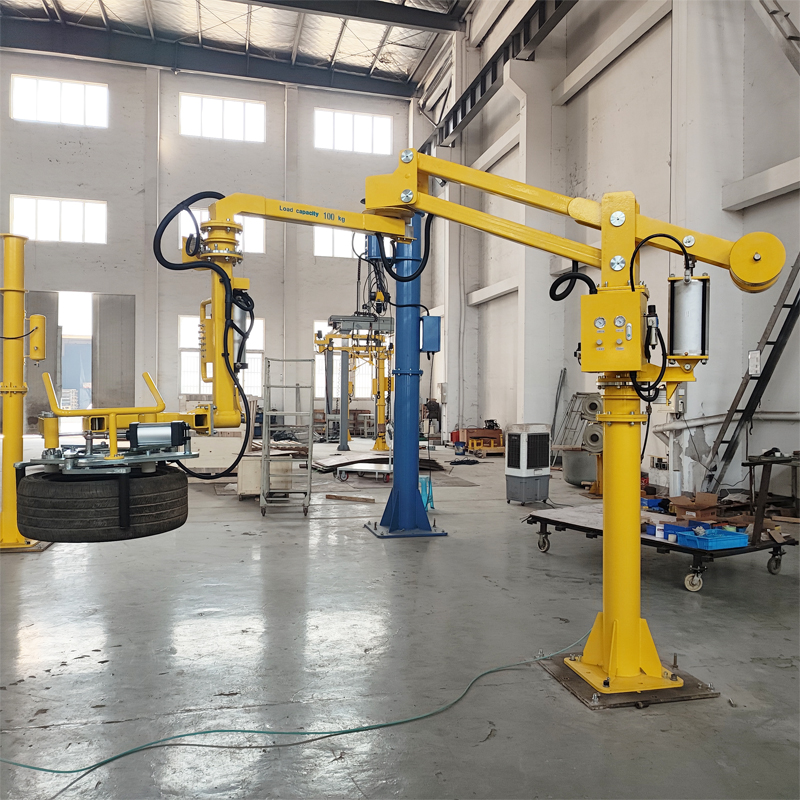
A rigid arm manipulator is an operator-guided, power-assisted handling device that uses an articulated rigid arm (not a cable) to move a load through a defined work envelope (the 3D space and motion path required for the task). Depending on configuration, it can lift, hold position, and allow controlled rotate/tilt for placement.
The key word is rigid: the structure is designed to resist sway and keep the load stable during positioning.
It’s often confused with nearby categories:
- Hoists / cranes: great for vertical lifting, but not always ideal for precise orientation control at the point of assembly.
- Vacuum tube lifters: excellent for fast vertical pick-and-place on suitable surfaces, typically with different reach/orientation trade-offs.
- Industrial robots: best when you need repeatable automation at speed—along with the budget, programming, and safeguarding that come with it.
For a concrete view of how rigid-arm configurations are commonly packaged, see TIANSHILI’s rigid arm manipulator examples.
Step 1: Define the “load package” (this is where most specs go wrong)
A manipulator rarely fails because the arm can’t lift the part. It fails because the real load is bigger—and less stable—than anyone wrote down.
Your load package should include:
- Part weight range (minimum, typical, maximum)
- End-effector weight (end effector = the tool that contacts the part: gripper, clamp, vacuum pad frame, magnet, hook, custom nest)
- Any adapters, quick-change couplers, sensors, and fasteners
- Packaging/dunnage that gets lifted with the part
- Center of gravity (CoG) notes: where the load “wants” to tip, and whether CoG shifts during rotation
Step 2: Map the work envelope and motion path
“Reach” is not a spec. Your work envelope is the combination of where the load must go and how it must get there.
Capture these items before you talk to vendors:
- Pick and place coordinates (X/Y/Z) and any approach angles needed for insertion
- Required rotation/tilt under load (e.g., rotate for alignment, tilt to clear a lip)
- Obstructions: guarding, conveyors, racks, posts, machine doors, fixtures
- Operator access zones (where hands must be during alignment)
- A defined safe park position for changeovers and breaks
If you want a structured template for documenting this, the industrial manipulator arm buyer’s guide walks through the envelope-first method in a plant-friendly format.
Step 3: Choose the right end-effector strategy
Most rigid arm manipulator projects are end-effector projects.
Match the tool to the “bad day” conditions, not the best case:
- Mechanical grippers/clamps: strong, tolerant of oily/dirty surfaces if designed well; require reliable grip surfaces.
- Vacuum tooling: efficient for flat, non-porous surfaces; sensitive to leaks, contamination, and surface variability.
- Magnetic tooling: useful for ferrous parts; requires attention to surface condition, residual magnetism, and part release behavior.
- Custom nests/fixtures: best when orientation must be repeatable and foolproof.
Define unacceptable grip conditions in writing (e.g., “must not pick if surface is wet/oily,” “must not deform carton,” “must not scratch finished face”). That’s how you prevent “it works in demo” surprises.
Step 4: Use a decision checklist to select the right rigid-arm configuration
Below is a practical selection checklist. You can use it to screen designs and avoid over-specifying.
- Payload window: Does the system handle your maximum load including tooling with margin?
- Stability at reach: Does it remain controllable near the edges of the envelope (no drift, no springy feel)?
- Degrees of freedom: Do you need simple lift/position, or controlled rotate/tilt for insertion and alignment?
- Position hold: When the operator releases the handle, should the load stay put?
- Changeover behavior: Can you swap tooling quickly and repeatably?
- Duty cycle reality: Is it used continuously, or in bursts during peaks?
- Maintenance access: Are wear points accessible without dismantling the cell?
Step 5: Safety and compliance considerations (US plants)
Rigid arm manipulators sit in a space that’s easy to underestimate: they’re not “fully robotic,” but they can still create serious hazards.
Plan safety from the task backward:
- Risk assessment: Document pinch points, crush zones, drop hazards, and unexpected motion. Validate the assessment with operations, maintenance, and EHS.
- Safeguarding: Use appropriate guarding and interlocks where an operator can enter hazardous zones during motion.
- Emergency stop (E-stop): Confirm E-stop location and behavior is consistent with your cell’s standards.
- Lockout/tagout (LOTO): Ensure maintenance procedures include control of stored energy (especially pneumatic systems).
- Standard work and training: “Safe when used correctly” isn’t enough—operators need a repeatable method that holds up under production pressure.
The goal isn’t paperwork. It’s preventing informal workarounds that eventually turn into incidents.
Step 6: Integration checklist (utilities, mounting, commissioning)
Integration risk is usually the biggest driver of downtime—not the manipulator hardware.
Confirm these items early:
- Utilities: air pressure/flow availability (and air quality), electrical requirements, noise constraints
- Mounting: floor/column/ceiling constraints, slab capacity, anchor locations, clearances
- Cell layout: service access for maintenance, hose/cable routing, interference checks with guarding
- Acceptance tests: what “done” means (safe operation at target pace, tool change repeatability, position hold, training completion)
Post time: Apr-20-2026